Since some time, I’m owner of a BMG Mini May.

(Picture: Brian May Guitars)
A great little travel guitar. Just very limited with the single pickup. I plan to change that; that’s the idea 🙂 … and since I’m going to tinker with the little beauty, let’s call her “Tinkerbelle”.
Her big relative, Brian May’s Red Special, is a well-known iconic guitar; it has a quite unique configuration with three pickups in serial configuration that can be switched on individually and have their phase reversed. Three pickups should fit on the little one as well. Original-compatible switches would be a bit more problematic. Brian May used six switches back then; on the Mini May this would look … well, rather crowded. My plan is to use three slide switches with three positions instead – off in the middle, a phase in each of the side positions. That should fit nicely without deviating too far from the original design.
Design Phase
… the Phase I normally like the most 😎
The big original one uses Burns Tri-Sonic pickups. They are easily available, just at rather high prices; since the guitar itself wasn’t expensive … hmmmno. I got them from China; supposedly Burns originals, made in Korea, a complete set for less than 30 Euros. I’m looking forward to hearing their sound, but implementing them will presumably take quite some time. Below the scratch plate, the Mini May seems to be massive wood, so routing cavities needs to be done … and I’ll try that on other things first.
To come close to the original design, I’ll use Switchcraft DP3T On-On-On switches, like the ones Fender puts in the Mustang range. With a white head, they’re not so easy to get; obviously, black ones are far more common, but they don’t fit the overall design as well. Until now, I’ve only found a source on Ebay. No problem – three of them, two, one, mine 🙂
The next physical step will presumably be to take off the scratch plate and put it into the scanner; I plan to have a laser cut scratch plate made out of acrylic glass. There are manufacturers that can do that based on vector graphics. This should look far better than anything I could do with drills and files; besides, I’d like to keep the original scratch plate intact.
… yeah, but how?
Of course, the switches are very interesting. My google fu seems to be weak nowadays; I couldn’t find schematics for the May circuitry with these DP3T sliding switches on the Internet. Slightly strange, since that brings the same variability as the original’s 6 switches, without any comfort or control loss; the current setting is even easier to see at a glance. Oh well, I should be able to do it on my own … so how do I get these DP3T switches to do what I want? Hmmm…
In principle, their mode of operation is simple: two rows of 4 contacts each. In the upper switch position, the uppermost two contacts of each row are connected, in the middle position, it’s the middle contacts, and in the lower position it’s the bottommost two contacts of each row. That has to be wired up somehow so that the pickup is put into the signal chain in one phase when the switch is in the upper position, removed from the chain in the middle position, and put in the signal chain in the other phase when in the lower position. I spent some hours decorating page after page with scribbled schematics that all had the little flaw of working in at most two of the three positions 😎 … then I was fed up. I’m no electronics engineer who simply knows how that’s done. But a programmer … so? This problem should be easily solvable with a computer program!
And indeed it was. Writing the program consumed two more hours, but in exchange it spit out three(!) different ways of doing it in as many minutes that do exactly what I want. This one it’s going to be:
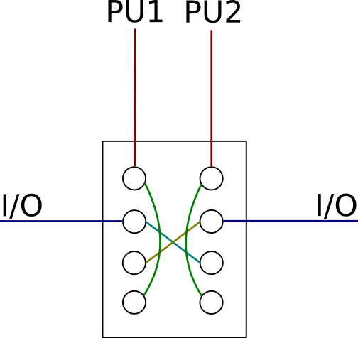
Simple, elegant and symmetric. The other solutions are asymmetric, which I don’t like as much.
And if someone is having lots of fun now at my expense, since I redeveloped the wheel with CAD – have fun, I’m doing this for the first time 🙂
And this would be the complete Red Special compatible schematic:
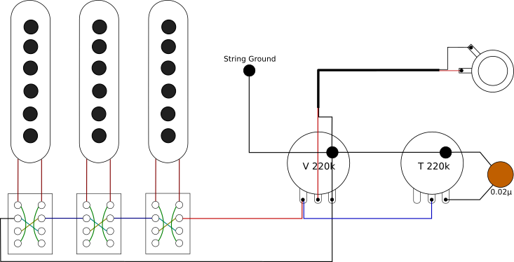
I haven’t looked under the hood (or better, under the pickguard) yet to find out which potentiometer and capacitor values the Mini May uses, but if they aren’t too far off, I’ll simply leave it at what’s already there.
The next steps are clear, at least in theory – create a pickguard design and a routing template for the Tri-Sonic pickups. I’m aware of the fact that due to the totally different materials and geometry (the Red Special has 24 frets whereas the Mini May has only 18, and the Mini also predetermines a bridge pickup position that’s not matching the Red Special’s) I won’t be able to completely recreate the sound, but hey … close is good enough for me.
… or so.
Just for completeness’ sake, I let my simple brute-force program spit out all possible solutions. Here they are, making it easy to see why I chose the above one:
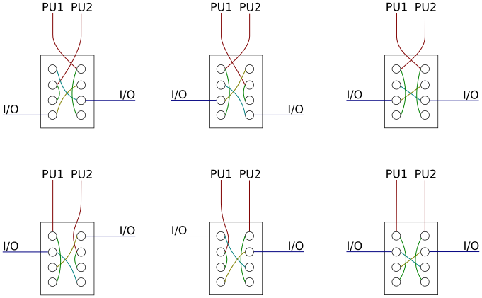
… it’s simply the most elegant one.